2.9 Load Plans
To populate the knowledge graph in the Data Context Hub with data we have to perform two main tasks:
- Load the data from the source into the staging layer
- Process the graph
Load Plans enable the the user to setup workflows of automation steps enable the triggering of data load and graph processing.
Create Load Plan
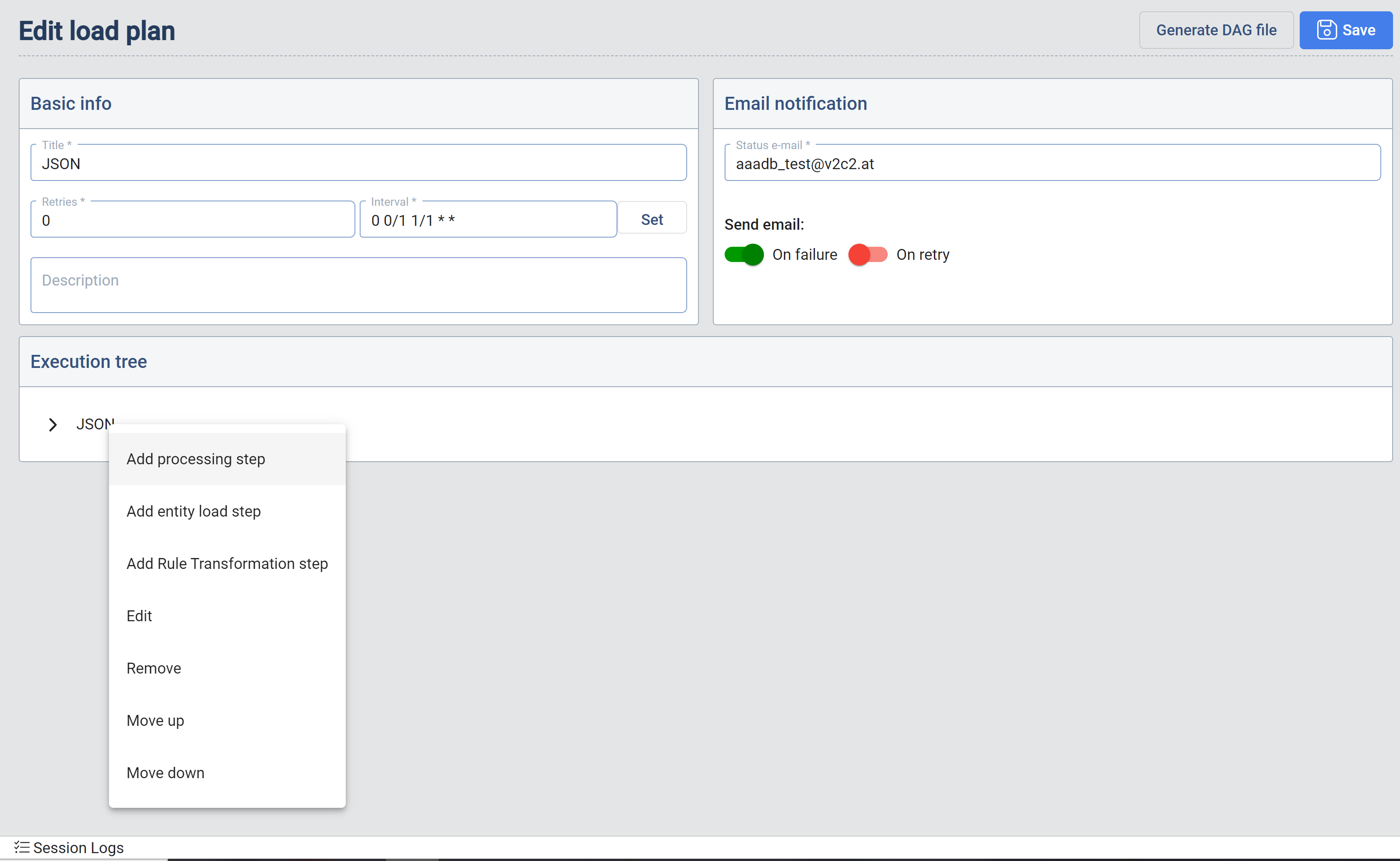
The Load Plan consists of two sections that define it: the parameters for execution and notification and the Execution tree which has the information about the Target Entities to be loaded.
Parameters for execution and notification
Set (interval): When the user hits the set interval button the Interval Definition dialog appears. The user has the ability to specify the execution schedule of a particular Load Plan. The output of the interval definition is a CRON expression which is visible in the Interval text box after confirmation.
Retries: Is the number of attempts the Data Context Hub load plans will perform a retry in case of a failure.
Generate DAG File: In order to deploy the defined Load Plan the user needs to generate a DAG File. The Data Context Hub utilizes the Data Importer. platform to implement scheduled workflow executions.
Directed Acyclic Graph (DAG) is a collection of all the tasks you want to run, organized in a way that reflects their relationships and dependencies. In other words, a DAG is a way to represent a workflow in Apache Airflow.
Each node in the DAG represents a task, and the edges between the nodes represent the relationships and dependencies between the tasks. The tasks in a DAG can run either in sequence or in parallel, and you can use conditions to control the flow of tasks based on their success or failure. The key feature of a DAG is that it must be directed (all edges must have a direction) and acyclic (there can be no cycles or loops), which ensures that tasks are executed in a correct order. When a new DAG gets generated it can take about 30 seconds until it get executed by the system.
Email notification: Is the E-Mail address to which a status E-Mails is sent in case of a failure.
The Data Context Hub Load Plans can convert the defined Execution Trees into DAGs and deploy them to the configured Airflow instance.
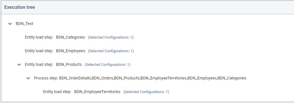
Execution Tree
The user defines a workflow by building a tree data structure. Each node in the tree represents a task. A node can be added, edited, positioned or deleted by click on it with the left mouse button.
- Load Step: A load step triggers the loading of data into a particular Target Entity. When adding a load step the
Add entity load stepappears. The users can select the Target Entities that should be included.
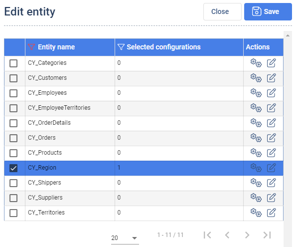
For each selected Target Entity, the user can select a particular configuration cog icon and the Load type. As stated in the Data Importer section, a Target Entity definition can have multiple data pump configurations associated.
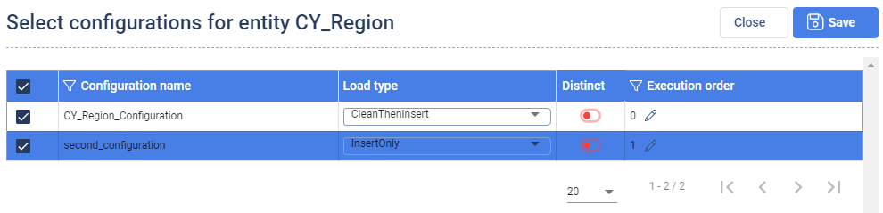
In the column Execution order the order, how the configurations should be executed can be determined. It is necessary to select at least one configuration for the data import to be successfull.
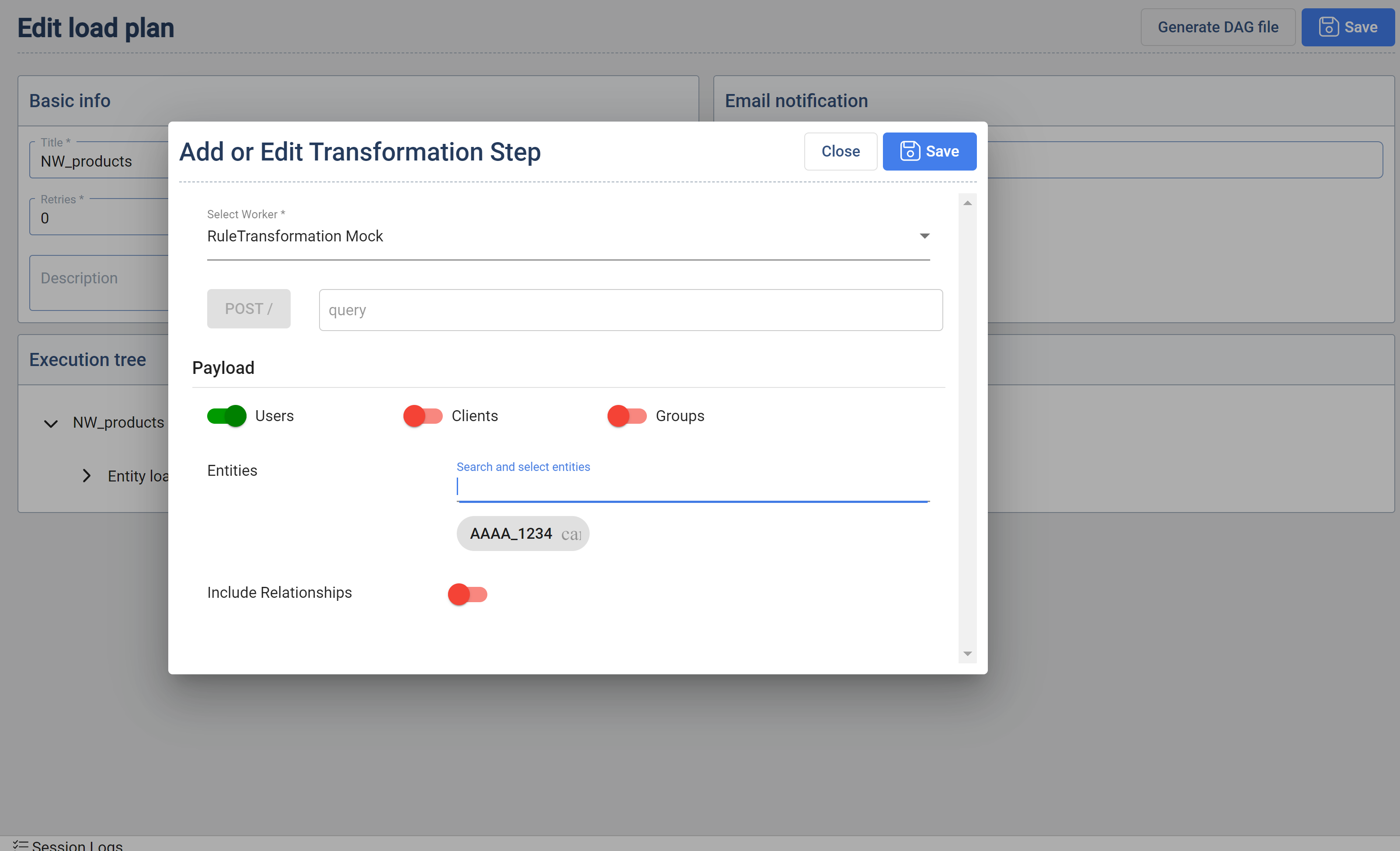
- Rule Transformation Step : When creating or editing a Load Plan it is now possible to add Rule Transformation steps.
Mandatory Fields
- Select Worker Dropdown : Lists all workers registered with type of Rule Transform
- One of the three Users,Clients,Groups should be enabled (multiple can be selected)
- At least one of the entities should be selected.
Optional Fields
- endpoint that should be called when this step is executed (default = /)
- Include relationships: default = false
- Override feature: The option for overriding of parameters,
refers for the parameters related to a data pump referenced in the selected configuration. The data pump parameters have a primary setting which is considered, if no override is set. Working with data pump is defined in the section related to defining Data Pump Containers. This is useful for example when data pump would contain a paging parameter. The user has in this case the ability to create multiple load steps each time for a different page or another parameter via the overrides. This enables the user to define multiple sources from which the data is pulled and integrated into one Target Entity. The override feature can be found when the user opens a Load step and clicks on the
pencil and papericon in the actions column.
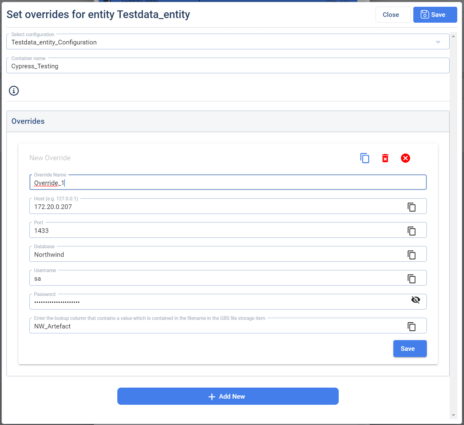
To set up an override, the user has to select a configuration beforehand. Then the user has to click on the button Add new to create a new override. The user then can adapt the parameters of the override to the desired ones to cofigure the override. If it is needed, the user can add more overrides and configure these. To save an override an override name is mandatory. Each override creates a new import job for the GBS when the Loadplan is executed. If overrides are set, only these overrides defined are loaded, the original configuration is not taken into account. Overrides are connected to the configuration that was selected. So it is possible to set different overrides for different configurations.
-
Processing Step: The processing step enables the user to define a set of Target Entities which be processed in a certain Load Plan step. The concept is the same as described in the section related to Graph Processing. The user here has different options to select in the processing section:
Clear- which clears the selected entities from the graph,Clear and Process- clears the selected entities from the graph and processes them afterwards,Process- just processes the selected entities. -
Edit: Allows the user to edit an existing step.
-
Move up/down: Allows the user to move change the order of the steps by moving them up or down.
-
Remove: Deletes a step.
When building the Execution Tree, the user can define the sequence in which the steps will be executed. The basic rule defines that all the children of a parent node can roll in parallel. But the children are always executed after the parent is finished.
Let's take for example a case where all the load and processing should run in sequence and no parallelization would be permitted. In this case the all the nodes in the tree would have one parent (exempt the first) and one child (exempt the last).
- Placeholders: The user has the possibility to work with predefined placeholder values they are parsed and replaced by GBS before they are send through the Data Pump (part of an Override).
Syntax:{"Placeholder": "", "Format": ""}, e.g.http://host:4028/api/files/Test.json&from={"Placeholder": "today", "Format": "dd/MM/yyyy"}
Supported placeholder:today(current day with time set to zero),now(current day and time),utcnow(current day and time in UTC),yesterday(yesterday with time set to zero)
Format: Definition of the format for the placeholder (currently only DateTime). e.g.dd/MM/yyyyfor 20/11/2023 (more Information)
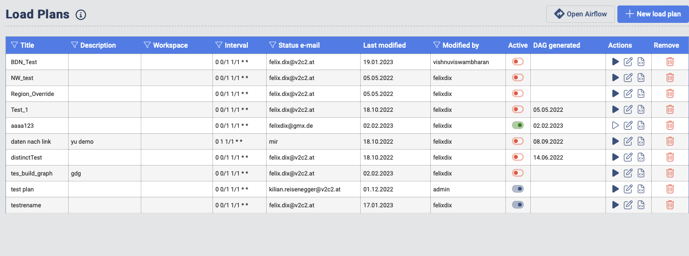
Load Plan overview
Active Column: Activate or deactivate a current Load Plan.
Actions Column: In this actions column the user has the ability to:
- Start a Load Plan manually (Play Icon)
- Edit and existing work flow (Edit Icon)
- Re-generate a DAG file (DAG Icon)
DAG Generated: This provides the information when the current DAG deployed on the associated AirFlow instance is deployed. In case the user changes and saves a Load Plan, the changes are not automatically propagated to the current DAG deployed on the AirFlow instance. The user needs to re-generate the DAG in order to deploy the create changes.